Elmer's "scotty" engine........a build log

The #1 community for Gun Owners in Indiana

Member Benefits:

  • Fewer Ads!
  • Discuss all aspects of firearm ownership
  • Discuss anti-gun legislation
  • Buy, sell, and trade in the classified section
  • Chat with Local gun shops, ranges, trainers & other businesses
  • Discover free outdoor shooting areas
  • View up to date on firearm-related events
  • Share photos & video with other members
  • ...and so much more!
  • 55fairlane

    Master
    Rating - 100%
    4   0   0
    Jan 15, 2016
    2,261
    113
    New Haven
    I am a member of The Machinist Group of Northeast Indiana , and this year's group project is to build Elmer's "scotty " engine. All the members are going to build this engine.
    I invite you to follow along with me. But first some background on Elmer & alterations to the build.
    Elmer Verburg was an electrical engineer with a passion for building running model engines. Thru out the 70's & 80's these engines were published in several magazines. Around 1988 Elmer published a book with all of his engine designs & construction notes in it. A hard bound original copy sells for $200 plus dollars. Luckily Elmer said apon his passing, the book was to distributed free among the masses.
    The name "scotty" comes from the scotch yoke arrangement at the crank. Simple put a scotch yoke has a pin the slides in a slot, turning rotating motion into linear motion.
    Some of the alterations I am doing include scaling the engine up twice sized, that will make the bore ¾ inch x 1 inch stroke.
    Here is a YouTube video of Elmer's "scotty " engine ,

     

    55fairlane

    Master
    Rating - 100%
    4   0   0
    Jan 15, 2016
    2,261
    113
    New Haven
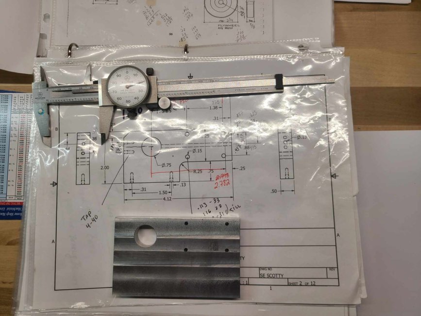
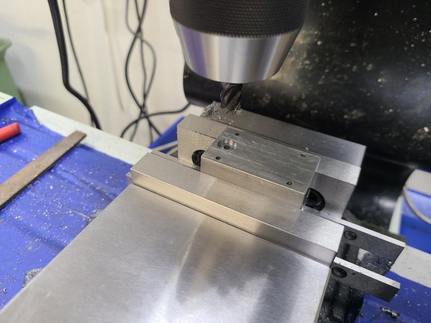
    Step 1 build the engine frame, simple part , done in 7075 aluminum. The bore for the (plain ) bearing was located (the ¾ hole in the part) and all other dimensions were brought off the bore to keep everything true to the center line of the rotating assembly .
    received_420034500400251.jpeg
     

    55fairlane

    Master
    Rating - 100%
    4   0   0
    Jan 15, 2016
    2,261
    113
    New Haven
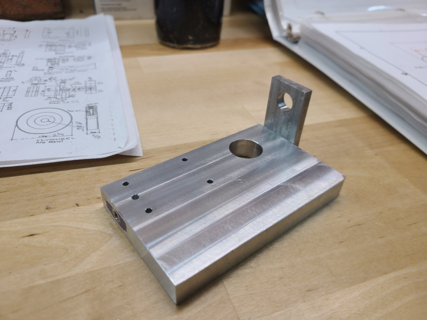
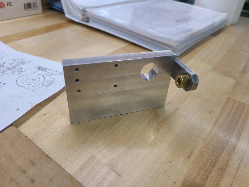
    Next I made outboard connecting rod support, not near as elegant as Elmer's but very functional. I added a leanth of yellow brass (held in place with Loc-tite) as additional bearing support for the "con-rod"
    Resized_PART_1710539507405_Resized_20240314_192030.jpeg Resized_PART_1710632785394_Resized_20240315_174413.jpeg
     

    55fairlane

    Master
    Rating - 100%
    4   0   0
    Jan 15, 2016
    2,261
    113
    New Haven
    Next it came time to machine up the cylinder, I chose to make mine from steal, A) This would allow me to lap the bore to a very fine finish, B) allow me to use an aluminum piston (this keeps the rotary mass down) & C) I own the steal, no need to buy a hunk of metal.
    This is when things went a drift, it became apparent to me that the steal I have is tool steal , probably a chrome-moly ....ugghhh carbide endmills and go slow. Took a week to get the cylinder down to size.
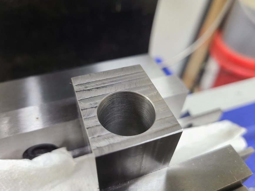
    Next set to drill & ream the ¾ inch bore, disaster struck, as my reamer picked up a shaving on a flute or something, the bore look like I finished it with a concrete drill. Resized_Resized_20240328_153210.jpg
    In our next installment, I will make a lap & see if we can get a finish on the bore, before removal from the vise.
     

    55fairlane

    Master
    Rating - 100%
    4   0   0
    Jan 15, 2016
    2,261
    113
    New Haven
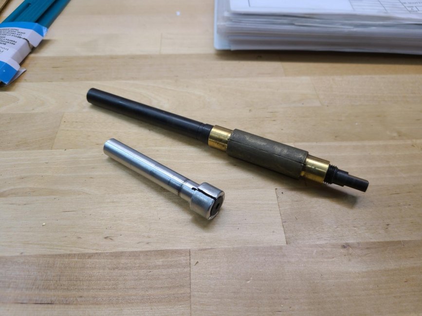
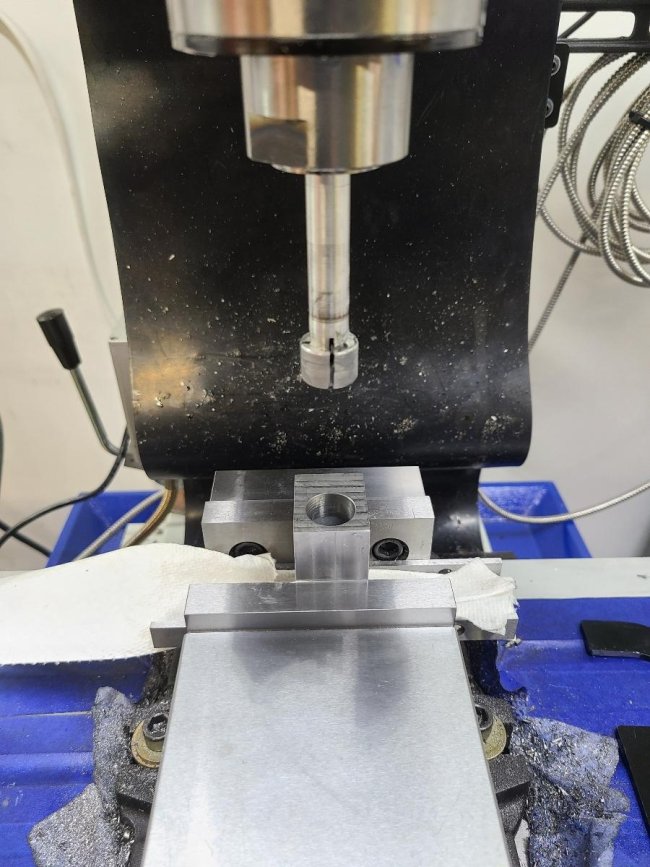
    In this picture you will see the aluminum lap & a commercial produced unit I own. What is "lapping " you ask, think ultra fine grinding for a super smooth finish.
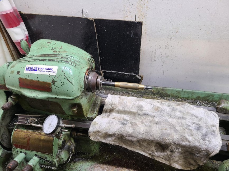
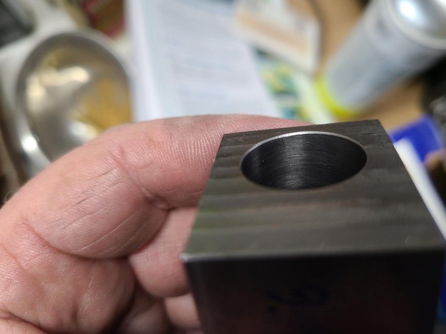
    Diamond dust, in a grease slurry was introduced to both the lap & the bore, at 100 rpm the lap was run thru the bore. After no more resistance was felt, the bore was cleaned, the lap was expanded & fresh lapping compound was introduced.
    A few strokes of my shop made lap, pull the part, wash it down, toss the commercial lap in the lathe & super finish the bore. Resized_Resized_20240328_153202.jpg Resized_Resized_20240328_155609.jpg Resized_Resized_20240328_163605.jpg my next step is to return the cylinder to the mill, drill & tap the 4 attachment points & the intake passage.
    You may note my cylinder is open on the end, I will "turn up" a cap when I am done and fix the cylinder closed with the cap & 4 screws.
     

    55fairlane

    Master
    Rating - 100%
    4   0   0
    Jan 15, 2016
    2,261
    113
    New Haven
    Cylinder got finished, 4 holes drilled & tapped (4-40) , steam inlet drilled , counterbored for an "O" ring , as a gasket, "O" ring is .070 thick (or profile in o ring terms) counterbore is .068 deap, allowing for .002 press.
    Resized_Resized_20240403_161500.jpg
     

    55fairlane

    Master
    Rating - 100%
    4   0   0
    Jan 15, 2016
    2,261
    113
    New Haven
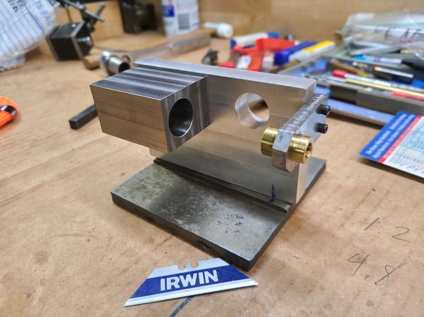
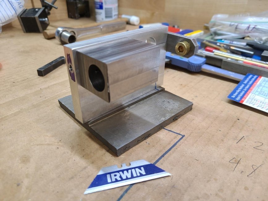
    I used a "found" piece of material for the base, did some drilling, tapping, countersink for tapered head screws & the base is mated to the frame. Not real happy with the fit, but that's cosmetic & can be fixed. The cylinder got attached to the frame. Next step is to make the crank bearing to fill that gaping hole in the frame Resized_Resized_20240403_193310.jpg Resized_Resized_20240403_193319.jpg
     
    Top Bottom